Fan Controller Board
A PCB board to power 4 12v PC fans.
Table of Contents
Introduction
I have a small TV stand to keep my game consoles in but even when I'm not gaming the consoles can heat up the compartments without good airflow. The Xbox One at least never seems to be cool, it wont be hot but it definitely wont feel like it's off.
So I've added a few temperature controlled PC fans which run constantly, their thermocouple is taped to the hottest part of the console. For the Xbox One it never seems to slow down. The PS4 fan seems to coast and the WiiU one hardly speeds up even during game play!
Anyways, it was a janky setup with a bit of veroboard breaking out a barrel jack and each fan plugged into it. Any small knock = fans disconnecting.
It was time to clean the situation up with a custom PCB.
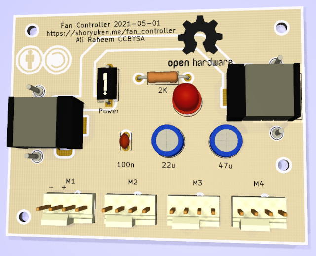
Figure 1: A KiCad render of the front of the PCB, a simple design that lets you power 4 fans, or 4 anythings for that matter. Only the first two pins of each 4x2.54mm header do anything. The capacitors are useless for the fans (I think) I wont connect them so as not to load down the SMPS - you can end up oscillating with the short circuit protection.
Design
I don't want anything special just a board that a 12V SMPS could plug into, maybe a switch or two. Some optional features I would or wouldn't want. The first revision is intended to be super simple, all the fans want are 12V and ground. The fans I have all have built in temperature control so I wont be tracking speed or controlling it. That isn't hard to do (frequency count the hall sensor output for the tachy, or PWM control the speed). Since it does pretty much nothing fan related (other than having space for a fan header which is just a 4x2.54mm header) I will put in caps and a power indicator so I could use it as a generic power supply.
Layout
The layout is simple, there is a power switch, option power indicator LED and decoupling capacitors (which are frankly pointless).
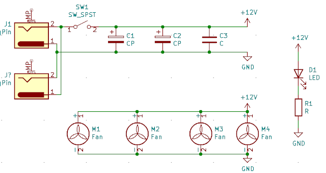
Figure 2: The bare schematic a barrel jack powers the supply through a switch.
PCB
There are two points to solder in the barrel jack with opposite tip/sleeve polarity. You can put in up to 3 capacitors. I reckon I will jumper the switch (they are suprisingly expensive) and omit the LED cause I don't need more random light in my bedroom - not that it'd be bright at a Vfd of 2V, 2kΩ gives about 5mA on a 12V supply. I'm not yet sure about the position of mounting holes. This design is currently untested but I quite like the way it looks in white soldermask as in Figure 1. I'm still playing with the design but then I'll send it to JLCPCB for the first revisions. The majority will remain unpopulated. But I could use it for a generic power supply board.
Files
Changes
- 01-05-2021
- First version