Active Bandpass Filter
Dual Opamp Based Active Bandpass Filter
Table of Contents
Introduction
A dual opamp based active bandpass filter, I’m using the LM358. The board uses one half of the LM358 to create a virtual ground and then the other one to amplify between a low pass and high pass RC network. It’s laid out like this to simplify as much as possible design of each stage. The two 100K resistors could be of any equal value, ideally large for power efficiency.
I think I might re-jig the board to use a cascade filter on both sides for sharper cut offs as when using it for a narrow band you end up with reduced gain at the centre frequency.
The last version was made by OSHPark. The cost was $9.10 for 3 boards.
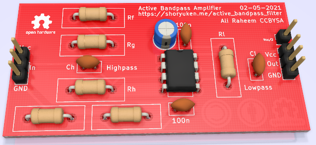
Figure 1: KiCad render of the PCB.
Pin Compatible opamps
I think the layout is pretty standard.
- LM358
- NE5532
- TLC27M7
Schematic
A full PDF for the schematic is attached below.
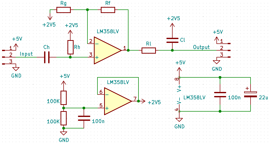
Figure 2: First the high pass filter decouples input, then it’s amplified as controlled by RF/RG. A virtual ground is also created with the two 100K resistors.
Between the RC filter networks is a non-inverting opamp amplifier with gain, Av = 1 + \(\frac{R_F}{R_G}\). The RC filters have a -3dB frequency at \(\frac{1}{2\pi{}RC}\).
PCB
The KiCad and Gerber files are attached below, the layout is simple. The power planes are fairly random with a small capactive effect for the VCC and \(\frac{V_{CC}}{2}\) supplies.
Professionally Made
I ordered a set from OSHPark, as always the purple and gold combo is absolutely banging.
| Manufacturer | OSHPark | JLCPCB |
| Layers | 2 | 2 |
| Width | 45.3mm | 45.3mm |
| Height | 26.0mm | 26.0mm |
| Boards | 3 | 5 |
| Cost | $9.10 | $9 |
OSHPark is a little more expensive (you get 5 boards from JLCPCB for the price of 3 from OSHPark), and the boards form OSHPark come with these nasty sprues that you have to file off (see in figure 3).
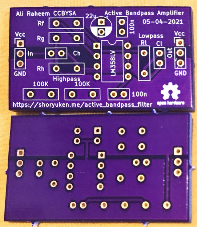
Figure 3: And a small but simple layout PCB for throughole parts. The boards came with jagged sprue reminants (below) I filed off (above).
That said I am very happy with the quality. I’ll likely order a set of boards from JLCPCB with a few changes, mainly using fullsized resistor footprints (1/4 W) and braking out \(V_{CC}/2\).
Example Usage
I’ve used it for a few small purposes, it was easy to solder even with the small resistor spacing. The new version will use full sized resistor spacing.
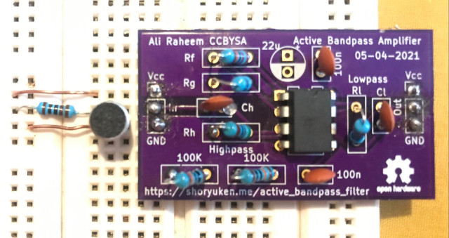
Figure 4: An electret microphone amplifier with a pass of 350-700Hz, output is clean around 0.2VPP. Soldering was… poorly done.
Changes
- 02-05-2021
- Breakout \(\frac{V_{CC}}{2}\)
- 01-05-2021
- Included OSHPark examples
- 08-04-2021
- Widen tracks, why so thin???
- 05-04-2021
- Switch back to dual OPAMP with single supply. Ordered from OSHPARK.
- 04-04-2021
- Switch to quad opamp with virtual ground.
- 03-04-2021
- High pass first to act as coupling stage.