A Simple Clock with LED Display Tuning Fork Clock
Part of my series on building a Turning Fork Clock
Table of Contents
Introduction
This is the "easy" part of my tuning fork clock a simple microcontroller design acting as a clock taking a 440Hz signal and driving a couple of 7segment displays.
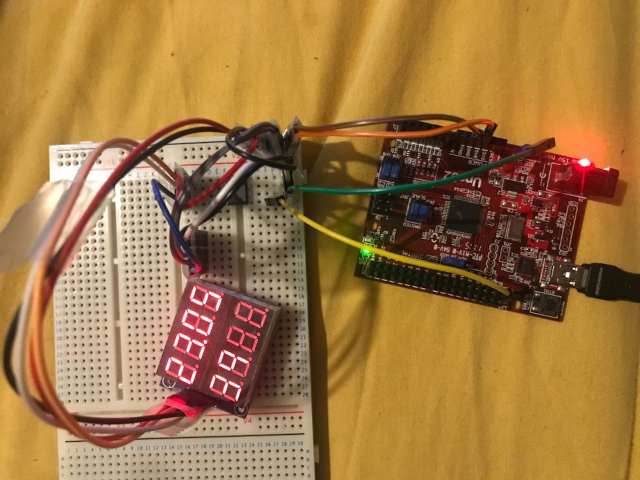
Figure 1: Here is the clock in action, you can't actually see the 12F508 behind the rats nest of wires. Pro-tip don't peel the film off the LED display, it's needed for contrast as you can tell from this photo (if you squint you can see the time displayed as 23:05:39). The board on the right is the ChipKit Uno32 which is used only to provide a 440Hz signal in lieu of the oscillator.
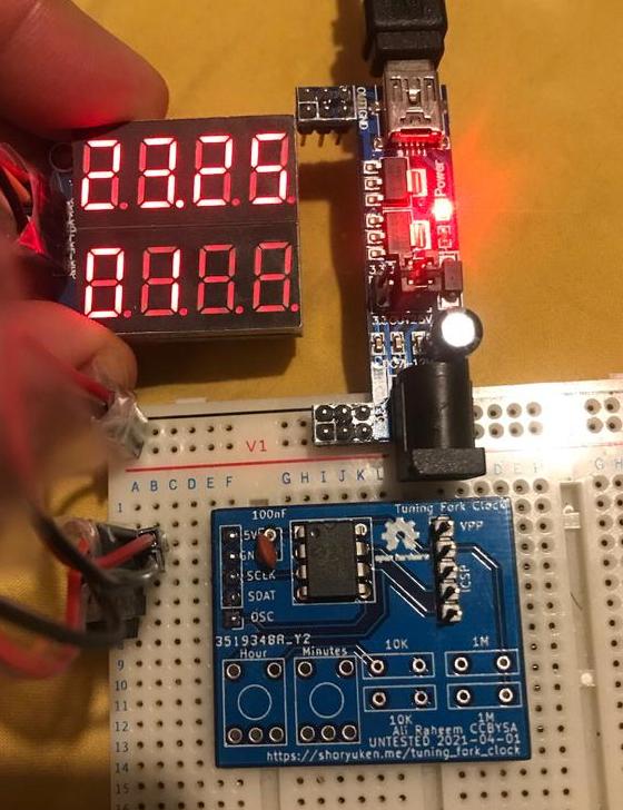
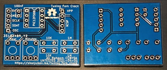
Figure 2: Testing the PCBs as produced by JLCPCB (design files at end of article).
Project files are attached at the bottom. The code is working but setting time is not tested, the PCB is untested and based on a schematic I have not tested! But the sketch of the pinout should be accurate.
Bill of Materials
- PIC 12F508
- Simple cheap and I have a few on hand. 5 IO pins, and 1 input only.
- 74HC164 2x4 7segment display
- Cheap off of eBay and easy to drive
- Clock source
- For testing I'm using a ChipKit Uno32, ludicrously overpowered just to generate a 440Hz signal.
Build
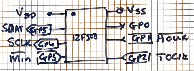
Figure 3: This is the pinout for the 12F508, the buttons to set Hours and Minutes are not currently enabled, they are active low and should use pull up resistors (internal pull-ups not used).
Code
The code is for the fairly ancient gpasm, one day I will update to XC8. The code listing is in the appendix below and along with Makefiles etc is in the zip file attached too.
The only interesting thing is it uses a round robin to pick which 7segment should be active, other than that it's a simple matter of keeping track of 440 ticks from the clock signal. The code is heavily commented because thats what I do when I write assembly!
The seven segment board takes a sclk and ser inputs, you clock in the 7segment data inverted then clock 8 bits to pick which display will show it. It took me a while to work that out as I could not find any datasheets for it.
Schematic
I used this schematic to make the PCB it's untested, and consider it likely I got SCLK and SDAT backwards at least. I added a token decoupling cap.
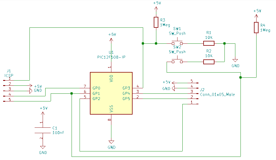
Figure 4: UNTESTED schematic layout I used to create the PCB
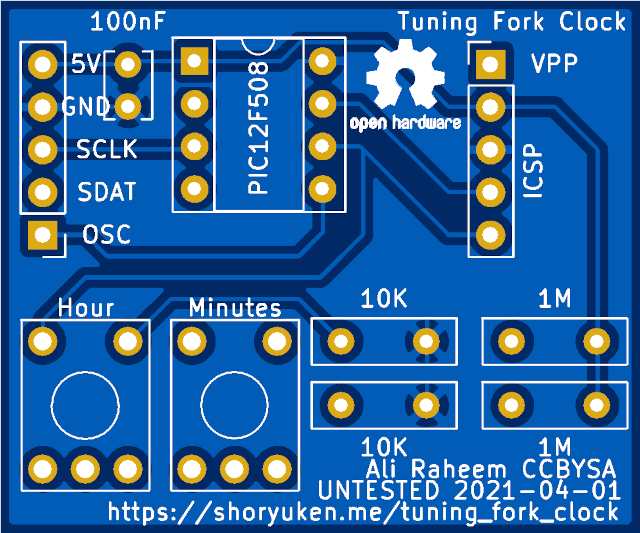
PCB
I have an untested logic board PCB it's double layer. Labels may be incorrect at least. KiCad and Gerber files provided.
Render
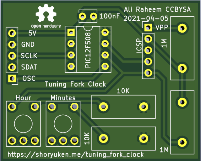
Figure 5: 3D view of topside, it's not very pretty.
Professionally made
Home Etch
I haven't tried this at home but for the entripid home etcher it looks relatively simple (although tracks are only 0.254mm).
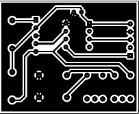
Figure 8: Reversed file for home etching (use the PDF linked below for better quality)
Conclusion
Now that really was easy… Hopefully the tuning fork oscillator circuit will work as well. Next step will be to use a nixie display, which is more a matter of expensive high voltage tolerate shift registers than more work. While the 12F508 is more than adequet for this, I think I will switch to a microcontroller with more power and pins for that (mostly for the pins!) Maybe an ESP32 as that means I can forgot button control.
License
This project, code and schematic is released under the GNU General Public License 3.0. Please contact me should you need a release under a specific other license.
Changes
- 05-05-2021
- Ordered boards from JLCPCB, realised too late that resistor footprint is tiny.
- 01-04-2021
- Add OSHW logo, clean up silkscreen.
- 31-03-2021
- Add pull up resistors.
Appendix
Code
;;; Ali Raheem - Copyright 2021
;;; GPL v3
;;; Tuining Fork Clock
;;; ==================
;;; Using A440Hz Tuning fork driving as an oscilator
;;; Output time to a shift register for 7segment LEDs
;;; BMIN allows you to set the minutes (active low).
;;; BHOUR allows you to adjust hours (active low).
;;;         ______
;;; Vss   -|*     |- Vdd
;;; SDAT <-|PIC   |-
;;; SCLK <-|12F508|<- BHOUR
;;; BMIN ->|______|<- Oscillator
;;;
;;; SDAT and SCLK control a 2x4 7segment displays via 74HC165
;;;
	list p=12f508
	include p12f508.inc
	radix dec

	__config 	_OSC_IntRC & _WDT_OFF & _CP_OFF & _MCLRE_OFF

cblock 0x07
	SECONDS_L
	SECONDS_H
	MINUTES_L
	MINUTES_H
	HOURS_L
	HOURS_H
	DELAY
	SHIFT_BUFFER
	SHIFT_COUNTER
	DISPLAY_INDEX
	SECONDS_OFFSET
	TMR0_OFFSET
endc

;;;
;;; Definitions
;;;

SDAT EQU 5
SCLK EQU 4
BMIN EQU 3
BHOUR EQU 1
ALL_OFF EQU 10

;;;
;;; Macros
;;;

;;; Skip if F == W
skip_Z macro FILE, N
	movlw N
	subwf FILE, W           ; Z = 1 if W == F
	btfss STATUS, Z         ; Skip if equal
	endm

;;; Skip if F <= W; W contains remainder
skip_LE macro FILE, N
	movlw N
	subwf FILE, W           ; W = F - W; W > F → C = 1
	btfss STATUS, C         ; Skip if no borrow
	endm

;;; Skip if F > W; W contains remainder
skip_GT macro FILE, N
	movlw N
	subwf FILE, W           ; W = F - W; W < F → C = 1
	btfsc STATUS, C         ; Skip if borrow
	endm

;;; Check if a FILE has reached MAX and overflow it
chkclk  macro FILE, MAX
	incf FILE, F
	skip_LE FILE, MAX
	goto loop
	clrf FILE
	endm

;;;
;;; Main code
;;;
	org 0
setup:
	movwf OSCCAL
;;; 1 Disable wakeup
;;; 1 Disable pullups
;;; 1 counter mode on T0CKI
;;; 0 RISING
;;; 0 prescaler for Timer0
;;; 000 1:2 prescaler
	movlw B'1110000'
	option

;;; GP2_T0CKI is input for Oscillator
;;; GP3/MCLR will be BUT0 for time adjustment
	movlw B'001110'
	tris GPIO               ; GP1, GP2/T0CKI,  GP3/mclr input

	clrf HOURS_H
	clrf HOURS_L
	clrf MINUTES_H
	clrf MINUTES_L
	clrf SECONDS_H
	clrf SECONDS_L

;;; Setting time
;;; Move times into registers
	movlw 2
	movwf HOURS_H
	movlw 3
	movwf HOURS_L
	movlw 5
	movwf MINUTES_L
;;; These variables may not start at zero

	clrf DISPLAY_INDEX
	incf DISPLAY_INDEX, F   ; We'll be rotating the index

;;; Here we adjust the timing per second/minute/hour/day
;;; It is better to adjust the TMR0 check value to make seconds accurate
;;; And use adjustment per minute/hour/day to fix the remaining offset.
;;; This can manage predictable clock drift but not instability
	clrf SECONDS_OFFSET     ; How many total seconds to add per hour
	clrf TMR0_OFFSET        ; Fractions of second This is over 220
	movlw 9                 ; 9/220 = 0.041s
	movwf TMR0_OFFSET

loop:
;;; Display index rotate
	bcf STATUS, C
	rlf DISPLAY_INDEX, F
	btfsc STATUS, C
	incf DISPLAY_INDEX, F

;;; Display round robin
	btfsc DISPLAY_INDEX, 7
	movf HOURS_H, W
	btfsc DISPLAY_INDEX, 6
	goto hours_l_with_dp    ; blink dp with seconds
	btfsc DISPLAY_INDEX, 5
	movf MINUTES_H, W
	btfsc DISPLAY_INDEX, 4
	movf MINUTES_L, W
	btfsc DISPLAY_INDEX, 3
	movf SECONDS_H, W
	btfsc DISPLAY_INDEX, 2
	movf SECONDS_L, W
	btfsc DISPLAY_INDEX, 1
	movlw ALL_OFF
	btfsc DISPLAY_INDEX, 0
	movlw ALL_OFF

	goto display

;;; This is just to blink the dp in time with seconds
hours_l_with_dp:
	movf HOURS_L, W
	call sseg
	btfsc SECONDS_L, 0      ; DP is on with odd seconds
	xorlw 1
	goto display_shift

display:
	call sseg
display_shift:
	movwf SHIFT_BUFFER
	call shift
	movf DISPLAY_INDEX, W
	movwf SHIFT_BUFFER
	call shift

;;; Display hold time
;;; ~750 microseconds total
	call delay
	call delay
	call delay

;;; TMR0 admin
	skip_LE TMR0, 220 ; 440Hz prescaled at 1:2 = 220.
	goto loop
	movwf TMR0 ; Not really needed, but in case some how we missed TMR0 == overflow value

;;; If minute button pushed or hour button skip to that part
;;; This increments the minute or hour per second.
	;; btfss GPIO, BMIN
	;; goto inc_minutes
	;; btfss GPIO, BHOUR
	;; goto inc_hours

;;;
;;; Second, Minute, Hour code
;;;

;;; Second
	chkclk SECONDS_L, 10
	chkclk SECONDS_H, 6

;;; Compensation code, this can adjust up to 10 seconds in 1/220 second increments
;;; If the oscilator is slow we can start the second count from more than 0
	addwf SECONDS_OFFSET, W
	movwf SECONDS_L
	movf TMR0_OFFSET, W
	addwf TMR0, F

;;; Minute
;;; Increment minutes, overflow as needed into hours
inc_minutes:
	chkclk MINUTES_L, 10
	chkclk MINUTES_H, 6

;;; Hour
inc_hours:
;;; Is it midnight? Did minutes overflow when hours are 23
	skip_LE HOURS_H, 2       ; 1 for 12 hour
	goto not_midnight
	skip_LE HOURS_L, 3       ; 2 for 12 hour
	goto not_midnight
	clrf HOURS_L
	clrf HOURS_H
	goto loop
not_midnight:
	chkclk HOURS_L, 10
	incf HOURS_H, F
	goto loop

;;;
;;; Functions
;;;

;;; shift out the byte SHIFT_BUFFER
shift:
	movlw 8
	movwf SHIFT_COUNTER
shift_continue:
	btfss SHIFT_BUFFER, 0
	bcf GPIO, SDAT
	btfsc SHIFT_BUFFER, 0
	bsf GPIO, SDAT
	bsf GPIO, SCLK
	rrf SHIFT_BUFFER, F
	bcf GPIO, SCLK
	decfsz SHIFT_COUNTER, F
	goto shift_continue
	retlw 0

;;; delay is a simple busy_wait delay function
delay:
	decfsz DELAY, F
	goto delay
	retlw 0

;;; sseg returns pattern for the 7segment display in w
sseg:
	addwf PCL, F
	retlw B'00000011'
	retlw B'10011111'
	retlw B'00100101'
	retlw B'00001101'
	retlw B'10011001'
	retlw B'01001001'
	retlw B'01000001'
	retlw B'00011111'
	retlw B'00000001'
	retlw B'00011001'
	retlw B'11111111'       ; All off
	end